Table of Contents
ToggleWater softeners solve a common household problem, hard water that clogs pipes, dulls hair, and leaves soap scum on fixtures. But if you’re planning to install one yourself or troubleshoot an existing system, understanding the water softener loop diagram is essential. This diagram shows how water flows through your softener, where valves control that flow, and how the system regenerates. Whether you’re a hands-on DIYer or just want to understand what a plumber is explaining, this guide breaks down the layout, components, and what each line and valve actually does.
Key Takeaways
- A water softener loop diagram is a schematic roadmap showing how hard water flows through your softener, where control valves direct the process, and how the system regenerates to remove calcium and magnesium minerals.
- The critical components of any water softener loop include the main resin tank, brine tank for salt storage, control valve (the system’s brain), drain line with a standpipe, and inlet/outlet connections that must never be reversed.
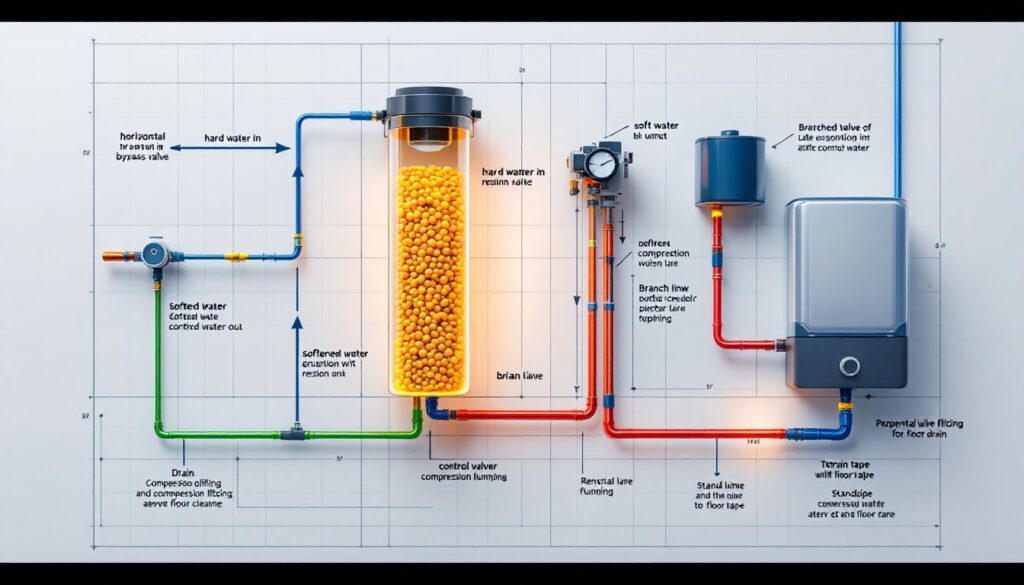
- Reading a water softener loop diagram requires tracing the path from the inlet through the resin tank to the outlet, then identifying the bypass valve, drain line, and brine connection—most use color coding (blue inlet, green outlet, red drain) explained in manufacturer manuals.
- Single-tank systems are most common for residential homes, though two-tank systems provide continuous soft water during regeneration, and specialized configurations like chlorine-removal or point-of-use (POU) softeners serve different household needs.
- DIY installation using your water softener loop diagram involves shutting off the main supply, installing a check valve, connecting inlet to bypass valve with proper fittings, positioning the drain line downward to avoid siphoning, and verifying all connections before reactivating water flow.
- After installation, maintain your softener by refilling the brine tank every 4–8 weeks depending on water hardness and usage, running manual regeneration cycles, and always checking local plumbing codes—some jurisdictions require a licensed plumber for water service work.
What Is a Water Softener Loop Diagram?
A water softener loop diagram is a schematic drawing that shows the plumbing layout and water flow path through a softening system. Think of it as a roadmap for your water, it illustrates where water enters, how it’s treated, and where it exits. The diagram also marks control valves, bypass options, and regeneration connections.
The “loop” part refers to the way hardness-causing minerals (calcium and magnesium) are removed in a continuous cycle. Hard water enters the resin tank, where ion exchange happens, and softened water exits. When the resin becomes saturated with minerals, the system regenerates, backflushing and running a salt brine solution through the resin to clean it.
Understanding this diagram before installation or repair saves time and prevents mistakes. It shows you where to connect inlet and outlet pipes, where to place the drain line, and how to position bypass valves for maintenance access.
Key Components of a Typical Water Softener Loop
A standard water softener loop includes several critical parts working together. The main tank (typically 8–10 inches in diameter, 48–60 inches tall for residential systems) holds the resin beads where the softening happens. Resin beads exchange sodium ions for hard minerals, gradually becoming exhausted and requiring regeneration.
The brine tank stores salt or potassium chloride solution. During regeneration, the control valve draws brine from this tank, flushes it through the resin, and removes accumulated minerals.
The control valve is the “brain” of the system. It directs water flow, monitors gallons treated, and triggers regeneration cycles (often at night to avoid service interruptions). Common types are mechanical (meter-based, regenerating after X gallons) or digital (time-based, regenerating on a set schedule).
The drain line carries wastewater during backflush and regeneration to a floor drain, sump, or septic system. Most residential codes require a standpipe (vertical drain line extending at least 6–12 inches) to prevent siphoning back into the softener.
Inlet and Outlet Connections
The inlet port accepts hard water from your main supply line. Most residential softeners use 3/4-inch NPT (National Pipe Thread) female connections, though some larger systems use 1-inch. The inlet is usually the top-left fitting on the control valve head.
The outlet port delivers softened water to your home’s plumbing. It’s typically identical in size and location (top-right on the control valve). Never connect inlet and outlet backward, it prevents proper water conditioning and damages the resin.
A bypass valve, often a three-way ball valve installed in-line, lets you isolate the softener for maintenance without shutting off the whole house. When turned to bypass, hard water skips the softener and flows straight through, letting you replace the resin tank or perform service work.
Bypass Valve and Control Valves
The bypass valve is your safety net. It’s a dedicated three-way manual valve (or sometimes integrated into the control valve head) that redirects water around the softener. If the resin tank cracks, the control valve fails, or you need to service the system, switching to bypass prevents water from backing up or creating pressure in a damaged tank.
The control valve manages the entire operation. It has separate ports: inlet (from hard water supply), outlet (to your home), drain (to wastewater), and regeneration input (from the brine tank). As water pressure pushes the valve through its cycle, ports open and close, controlling which direction water flows.
Many systems include a venturi valve (or ejector) to draw brine from the tank during regeneration. Water pressure powers this ejector, no electricity needed. Others use an electric brine valve for better control on all-electric softeners.
Flow rate and pressure rating matter. Residential systems typically handle 10–20 GPM (gallons per minute) at operating pressure, with a working pressure range of 20–85 PSI. Check your specific diagram to confirm your system’s ratings before connecting high-flow fixtures or appliances that might exceed these limits.
How to Read and Interpret Your Water Softener Diagram
Reading a water softener loop diagram takes practice, but follow these steps and you’ll decode it like a plumber.
Start at the inlet. Locate the arrow or line labeled “Hard Water In” or similar. This is where your main supply line connects. Most diagrams place it at the top or left.
Trace the path through the resin tank. The diagram shows water entering near the top, flowing down through the resin bed (removing hardness), and collecting at the bottom. Some systems show the flow path as a series of arrows or a shaded region.
Find the outlet. Hard water exits the top or side of the resin tank as softened water. The outlet feeds directly to your home’s plumbing or through an outlet check valve (a one-way valve preventing backflow).
Locate the bypass valve. It’s usually a three-way ball valve drawn as a corner piece near the inlet and outlet connections. One port accepts hard water in, one delivers softened water out, and the third branch skips the tank entirely. Rotating the handle 90 degrees switches between softening and bypass modes.
Note the drain line. Most diagrams show a separate line from the control valve or tank, running to a drain. It should slope downward and never pressurize (open to air or atmosphere).
Identify the brine connection. A smaller line links the brine tank to the softener’s control valve. During regeneration, the valve opens this port, allowing brine to flow into the resin tank. Residential systems usually include a float valve in the brine tank to prevent overfilling.
Colors and line styles vary, some diagrams use blue for inlet, green for outlet, red for drain. Your manufacturer’s manual explains their specific color scheme. Study yours before cutting any pipe.
Common Water Softener Loop Configurations
Water softener layouts vary based on home plumbing, tank design, and manufacturer. The most common setup is the single-tank system, where one resin tank handles all softening. Hard water enters, gets softened, exits, and regeneration occurs overnight or during low-use periods (typically 1–3 hours).
Some homes use two-tank or twin-tank systems for continuous softening. While one tank regenerates, the other supplies soft water. These systems cost more but suit high-water-use households (large families, frequent laundry) without service interruptions.
Chlorine-removal or combo systems integrate carbon filtration into the loop, removing chlorine alongside hardness. The diagram adds a carbon chamber before or after the resin tank. These systems require more frequent maintenance because carbon needs replacement every 6–12 months, depending on chlorine levels.
Backflush-only systems regenerate differently. Instead of a traditional control valve, they use a simple backflush head, water pressure alone reverses flow, pushing accumulated particles out the drain. These older designs are simpler but less efficient: they’ve largely been replaced by metered or digital control valves.
The point-of-use (POU) softener is a compact unit under the kitchen sink or mounted on a single faucet. Its loop diagram is tiny but follows the same principles: inlet, resin tank, outlet, and drain. POU units are affordable but condition only one water line, not the whole house.
Check your diagram to identify which configuration you have, it affects regeneration timing, maintenance intervals, and troubleshooting steps.
DIY Installation Tips Using the Loop Diagram
Before you cut any pipes, understand that water softener installation varies by location. Municipal codes differ, and some jurisdictions require a licensed plumber for any water service work. Check local regulations first, you may need a permit. If your home has a water meter, that’s typically the best supply-tap point for a softener. If you’re unsure about codes or pressure ratings, call a professional. Otherwise, here’s how to use your diagram:
1. Shut off the main water supply. Turn the valve at the meter or entry point and open an indoor faucet to depressurize the line.
2. Locate your supply line. Near the water meter, you’ll find a point to branch off. Cut the cold-water line using a hacksaw or tubing cutter (a tubing cutter gives a cleaner edge and is worth the $10 investment). Copper, PEX, or PVC all work: match your existing material.
3. Install a check valve in the inlet line. A 1/2-inch or 3/4-inch inlet check valve (depending on your system) prevents backflow if water pressure drops. Many residential softeners require this for proper operation.
4. Connect inlet to the bypass valve. Using the diagram, attach the inlet line to the “in” port of your bypass valve. Use Teflon tape and stainless-steel compression fittings (avoid brass for long-term durability). Tighten snugly but don’t over-torque, you’ll strip plastic threads.
5. Run the outlet to your home’s plumbing. From the bypass valve’s “out” port, connect the softened-water line. Use the same material and fitting type as your supply line. Most homes run 3/4-inch PEX or copper at this point.
6. Position the drain line. Slope the 3/4-inch drain tubing downward to a floor drain, laundry sink, or sump pit. It should never pressurize, leave the end open to air. If you’re draining to a septic system, check local codes: some jurisdictions restrict salt discharge. Use a standpipe (an open vertical section 6–12 inches above the drain entry) to prevent siphoning.
7. Add a shut-off valve downstream. After the softener, install a ball valve on the outlet line. This lets you isolate the system for future maintenance without affecting the rest of the house.
8. Verify all connections with your diagram. Double-check inlet, outlet, and drain ports match your schematic. Tighten every fitting. Turn the main supply back on slowly, watching for leaks around all compression connections.
Safety gear: Wear safety glasses when cutting pipes: wear gloves when handling Teflon tape or old scale buildup. If the water line is under pressure and you’re not confident, stop and call a plumber. Resources like step-by-step installation instructions for water softeners break down the process with detailed plumbing diagrams.
After installation, check the brine tank level and fill it per the manufacturer’s instructions. Run a manual regeneration cycle (most systems have a button on the control valve) to flush any resin dust before using the softened water.
Regular maintenance prolongs system life. Add salt or potassium chloride to the brine tank every 4–8 weeks, depending on water hardness and your family‘s usage. Many DIYers treat this like a seasonal task, refresh it when checking smoke detectors.